Force Gauges Calibration
Force gauges, load cells with or without display and force measuring systems, consisting of a force sensor and a display unit, should be regularly calibrated to proof the tracability to the international standards (SI system). The sensor elements used (strain gauges or piezoresistive elements) themselves, but more so the bonding with the sensor body, are subject to aging. The change in the measured values is less due to the use than to the environmental influences during storage and use.
It is recommended to set the calibration interval for new force gauges short to approx. 12 months. If after 3-5 calibrations it emerges that the aging processes and the associated drift of the measured values are low, the calibration interval can be increased. Strong humidity and temperature fluctuations should then be avoided in any case. Compared to other measuring devices for mechanical or dimensional variables, force and torque measuring devices show faster deviations due to environmental conditions than purely digital measuring technology.
In the event of overloading or after adjustment, existing calibration certificates lose their validity and must be renewed. In addition, it is always advisable to perform a calibration prior to an adjustment in order to be able to track long-term changes in the measured values accurately.
Calibration Laboratory
Required Equipment
The prerequisite for the calibration of force measuring devices and force transducers is that the calibration laboratory has a force reference standard measuring device. In these systems, gradually or continuously increasing or decreasing forces act on the device to be calibrated.
Three different basic principles are applied; direct load with masses (sketch 1), indirect load with masses and mechanical or hydraulic transmission and load with reference transducers (sketch 2).
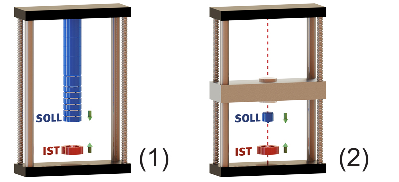
The direct load principle (sketch 1) "dead load machine" is carried out by interconnected masses, which act as a weight force on the force gauge. As a result, the lowest measurement uncertainties can be achieved. The individual masses must be coordinated with one another in order to be able to approach the load levels prescribed in the method exactly. In addition, these calibration machines must be adapted to the respective location of the laboratory. Apart from the local gravitational constant, the air buoyancy as well as further environmental and location factors have to be considered. With the most accurate systems of this type, which are installed at the Physikalisch Technische Bundesanstalt, measurement uncertainties of 2 x 10⁻⁵ can be achieved.
High forces can no longer be applied technically with direct load, so above 2 MN only indirect, hydraulically translated calibration systems come into question, whereby the transmission degrades the measurement uncertainty to 1 x 10⁻⁴.
It is easier to work with standard reference measuring equipment with reference standards (sketch 2). Here tensile or compressive force is applied to the device to be calibrated in a modified tensile tester with a high-quality force transducer, the so called reference standard. These systems usually work with a measurement uncertainty of 1 x 10⁻³, but have the advantage of a faster and continuous startup of the respective load level.
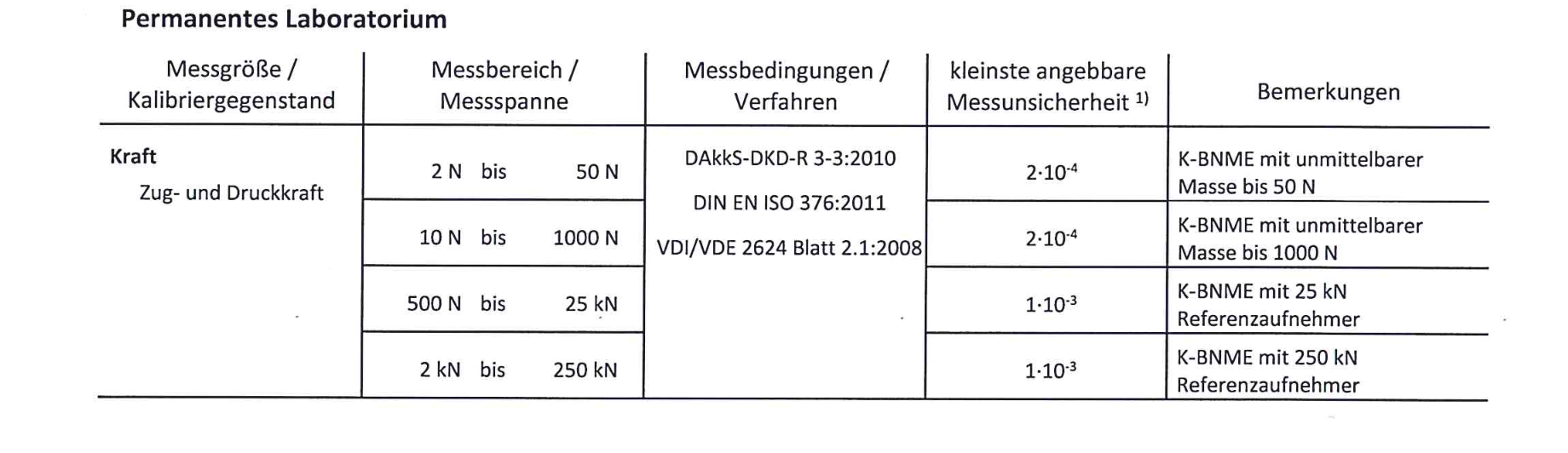
Competence
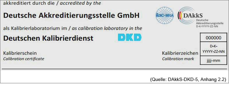
The requirement for the competence of a calibration laboratory and its employees is described in ISO 17025. A calibration laboratory should therefore be accredited for the respective measurand, for force for the SI unit Newton [N], the measuring range to be calibrated and the applicable standarized calibration procedures. This competence is regularly audited by DAkkS and confirmed in the annex to the accreditation certificate.
(Extract DAkkS - Accreditation certificate D-K-20121-01-01)
Calibration Procedures
With regard to the calibration procedures for force gauges and force transducers, there are significant differences, which depends on the type of measuring device to be calibrated and its use. The most common method is the DAkkS-DKD-R 3-3, with four different procedures that differ significantly in the number of force levels.
Calibration according to DAkkS-DKD-R 3-3
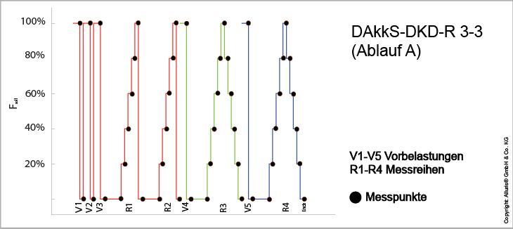
Full calibration according procedure A
The full calibration according procedure A allows to determine the essential characteristics of a force measuring device, a force transducer with display or a measuring chain consisting of a force sensor and a measuring device. For this purpose, at least 5 force levels are approached in 3 measurement series with increasing and decreasing loads.
Shortened methode B, C und D
In addition to the comprehensive procedure (methode) A, it is also possible to use shortened methodes if the calibration laboratory is accredited accordingly. For this, the laboratory must have special knowledge of the respective types of force measuring devices, since individual uncertainty contributions are not measured but must be taken into account in the measurement uncertainty of the overall system.
In method B, the comparative precision is not measured. Therefore, this method is suitable taking into account known influencing factors, which are included in the measurement uncertainty analysis, especially for handheld force gauges and measuring chains for which a calibration certificate according method A or ISO 376 is already available.
The method C consists only of an increasing and a decreasing series of measurements, therefore dispenses with both the measurement of the comparative precision as well as the measurement of repeatability. Both values must therefore be taken into account in the measurement uncertainty analysis with corresponding factors.
In method D, only increasing force levels are measured. This method requires that the force transducer is used only for the measurement of an increasing force and only in one effective direction.
Calibration according to ISO 376:2011
A calibration according to ISO 376 is the most complex type of calibration, since at least 8 load levels must be approached in 3 series of measurements. Therefore, this method usually applies only for high-quality load cells, which are used as reference standards or used to check the force measuring device of tensile testing machines and universal testing machines.
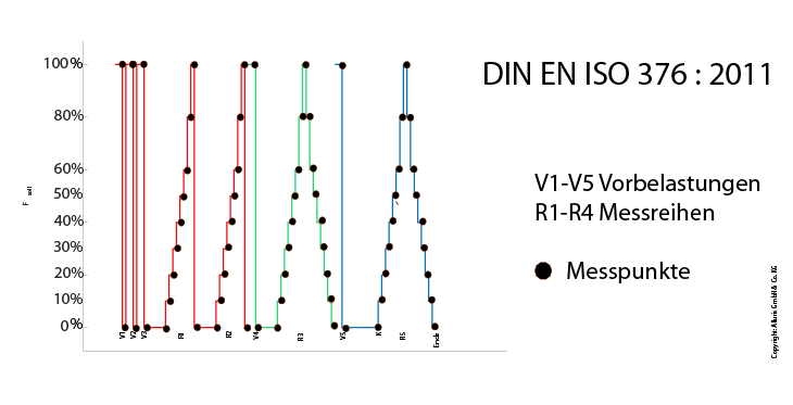
Calibration certificates according ISO 376 can also show voltage (mV / V) of the measurement output instead of the SI unit Newton [N]. For calibration, high-precision amplifiers are used, which have to be are also traceable to the standards of the PTB.
Calibration according to VDI / VDE 2624 sheet 2.1
For hand-held force gauges it is possible to carry out the calibration according to a simplified procedure, described in VDI / VDE 2624 part 2.1. The essential difference to the procedure according to DAkkS-DKD-R 3-3 is that the comparative precision is not measured but taken into account in the measurement uncertainty and the repeatability is determined only at one load level.
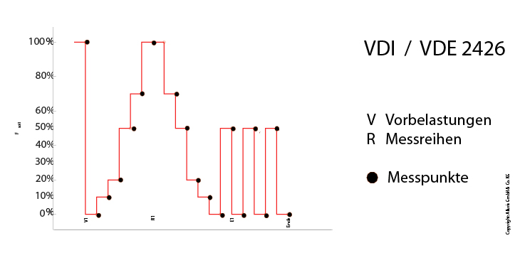
This guideline assumes that the comparative precision in different rotational positions, can not be adequately determined by a rotation of 120 ° due to different installation position for handheld force gauges, since the measuring device is used in all spatial positions.
Calibration result and calibration certificate
Calibration certificates in Germany are issued in accordance to the guideline DAkkS-DKD-5 "Instructions for creating a calibration certificate". This guideline fundamentally determines the content and form for all calibration certificates issued by the DAkkS accredited calibration laboratories. Only these calibration certificates may bear the seal of approval of the DAkkS, the DKD and, if applicable, for international recognition the ILAC-MRA seal. Colloquially, these notes are often referred to as "DAkkS certificates".
These certificates always list the calibration procedures used. These procedures have to be validated and audited by the national accreditation body DAkkS.
The calibration result must always take the measurement uncertainty into account. Only with a statement of conformity, which also includes the measurement uncertainty or a statement of the extended measurement uncertainty associated with each measurement result, the traceability of the measurement results is guaranteed.
Selection Criteria
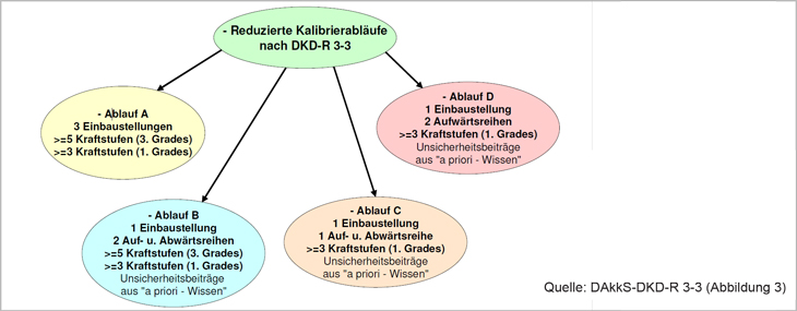
The most important selection criterion is first the optimal calibration procedure. The following flowchart summarizes the alternatives described above again.
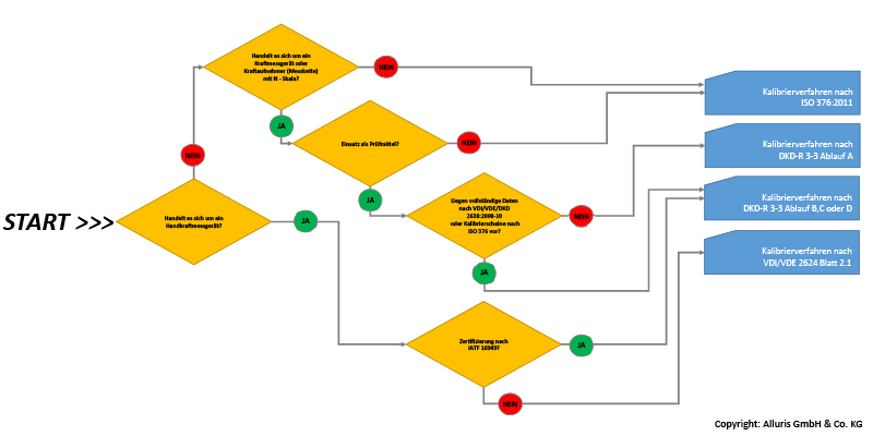
Once you have determined the approbiate procedure, you can use the accreditation certificate from your calibration service provider to determine whether it is accredited for the relevant procedure, the measurement range is covered by the accreditation, and the smallest measurable measurement uncertainty (CMC) of the laboratory meets your requirements.
The flowchart can be a help to find the right calibration procedure. Our Calibration Laboraty Service Team will gladly advise you personally. Call us or put your questions in the contact form.
Normative Verweise
Kalibrierverfahren
DAkkS-DKD-R 3-3 Kalibrierung von Kraftmessgeräten (zu beziehen bei: PTB Physikalisch Technische Bundesanstalt - Publikationen)
VDI/VDE 2624 Blatt 2.1 Messen mechanischer Größen - Anweisung zum Kalibrieren von Handkraftmessgeräten (zu beziehen bei: Beuth Verlag AG)
DIN EN ISO 7500 Kalibrierung und Überprüfung von statischen einachsigen Prüfmaschinen - Teil 1: Zug- und Druckprüfmaschinen - Kalibrierung und Überprüfung der Kraftmesseinrichtung (zu beziehen bei: Beuth Verlag AG)
DIN EN ISO 9513 - Kalibrierung von Längenänderungs-Messeinrichtungen für die Prüfung mit einachsiger Beanspruchung (zu beziehen bei: Beuth Verlag AG)
DIN EN ISO 376 - Kalibrierung der Kraftmessgeräte für die Prüfung von Prüfmaschinen mit einachsiger Beanspruchung (zu beziehen bei: Beuth Verlag AG)
Sonstige Richtlinien
DAkkS-DKD-R 3 Angabe der Messunsicherheit bei Kalibrierungen, ersetzt durch EA-4/02 M: 2013 (zu beziehen bei: Regelwerksportal der DAkkS GmbH)
DakkS-DKD-R 5 Anleitung zum Erstellen eines Kalibrierscheins (zu beziehen bei: Regelwerksportal der DAkkS GmbH)